1. What is an IGBT module?
In electric vehicles, renewable energy power generation, rail transit, and industrial automation, IGBT modules are evolving toward higher power density, smaller footprints, and higher junction temperatures. However, as chip power density increases, the available cooling space shrinks rapidly. Studies show that thermal issues cause more than 50% of integrated circuit failures; for power electronics, about 55% of IGBT failures are temperature-related. Traditional air cooling has a limited convective heat transfer coefficient (approximately 37 W/cm² at best) and bulky volume, making it inadequate for next‑generation power modules. liquid cold plate technology has emerged as a core solution for high‑power chip thermal management.

2. Thermal Challenges of IGBTs and Limitations of Traditional Cooling
An IGBT module generates significant heat. For a 100 kW inverter with 98% efficiency, about 2 kW of heat must be removed by the thermal management system. Moreover, heat distribution is not uniform; local hot spots on the chip surface can be much hotter than the average temperature, and these hot spots limit dynamic performance and service life.
Temperature strongly correlates with IGBT failure. A statistical study of wind turbine failures across 23 countries between 2003 and 2017 showed that IGBT module failure accounted for 22% of unplanned converter downtime – one of the most failure‑prone components in wind systems. Frequent acceleration/deceleration in vehicles causes severe power cycling and temperature swings, leading to bond wire fatigue, solder delamination, and other thermal‑fatigue failures. Thermal runaway can cause power loss in electric vehicles, a serious safety hazard.
From a thermal resistance perspective, IGBT heat dissipation is a multi‑layer series thermal resistance problem. Interface thermal resistance accounts for more than 60% of the total, making it the key bottleneck. Within the junction‑to‑case resistance, the DBC (Direct Bonded Copper) ceramic substrate is the dominant contributor (over 75%). Traditional air cooling suffers from three major limitations: low heat transfer coefficient, poor ability to eliminate local hot spots, and large system volume, conflicting with system miniaturization.
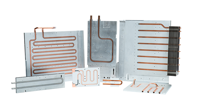
A liquid cold plate (also called a cooling plate, liquid cooling plate, or water cooling plate) uses forced liquid convection to remove heat. The working principle is simple: heat from the IGBT module transfers through a thermal interface to the cold plate base, then is carried away by the coolant flowing through internal channels; the heated coolant circulates to a heat exchanger, cools down, and returns.
Based on manufacturing processes and structural forms, four mainstream igbt cold plate types are used in engineering today.
3.1 Traditional Liquid Cold Plates
Traditional designs include drilled, assembled, welded, and tubed types. These have simpler processing, lower cost, and are suitable for low‑to‑medium power density IGBT modules. Among them, the tubed cold plate (or Tube Liquid Cold Plate) embeds copper or stainless steel tubes into grooves of an aluminum baseplate, fixed by brazing or epoxy. It offers better thermal performance and service life than basic drilled plates.
Tube liquid cold plates (also called water cooled cold plate or tubed cold plate) use copper or stainless steel tubes as coolant channels, embedded into an aluminum baseplate and fixed with thermal adhesive or brazing. Their advantages include simple manufacturing, low cost, and flexible tube layouts (e.g., serpentine or U‑shaped) that can match the IGBT’s heat distribution. They are suitable for medium‑power density, cost‑sensitive industrial drives and solar inverters. Typical tube diameter is 6–12 mm, and operating pressure is normally below 0.5 MPa.
FSW Liquid Cold Plates (Friction Stir Welding) use a rotating stir pin to generate frictional heat, plasticizing the material and creating a solid‑state weld between the cover and the grooved baseplate. This process produces no porosity, no cracks, and no filler metal, resulting in high weld strength, excellent sealing, and no flow channel deformation. FSW cold plates are ideal for electric vehicle traction inverters and rail transit converters where long‑term reliability is critical. Typical channel width is 4–10 mm, and pressure resistance can reach 1.5–2.0 MPa.
3.4 Extruded Liquid Cold Plates
Extruded liquid cold plates (or aluminium cold plate, aluminium cooling plate) are formed by aluminum extrusion using a dedicated die to produce multi‑parallel flow channels in one step, then cut, end‑sealed, and machined. The key benefits are high production efficiency and low unit cost, with consistent channel dimensions, ideal for high‑volume standardized production. However, the channels are usually straight‑through, limiting fin optimization. These are used in general‑purpose inverters and EV charging modules where power density is modest. Typical hydraulic diameter is 2–5 mm.
Brazed liquid cold plates (or brazed cold plate) are made by vacuum or controlled‑atmosphere brazing a stamped flow‑channel baseplate to a cover plate. This allows complex internal fin structures such as pin fins, oblique fins, and turbulators. Brazing offers very high design freedom, enabling enhanced heat transfer in a compact size, with good sealing and low residual stress. Brazed liquid cold plates are the first choice for high‑power‑density IGBT and SiC modules, widely used in premium EV main drives, wind converters, and high‑end industrial power supplies. Channel feature sizes can be as small as 1–3 mm; with pin fins, thermal resistance is significantly lower than extruded or tube types. Vacuum brazing is the most reliable process.
3.6 Comparison of Thermal Resistance and Structure Among Different Cold Plate Architectures
To assist engineering selection, Table 1 compares key thermal and structural parameters of the four igbt cold plates (including traditional tubed as baseline).
Table 1: Thermal resistance and structural comparison of different liquid cold plate architectures
| Architecture Type | Relative Thermal Resistance (baseline = tubed) | Relative Pressure Drop (baseline = tubed) | Internal Channel / Fin Features | Manufacturing Process | Suitable Power Density Level | Typical Applications |
|---|
| Tubed (Tube) (traditional) | 1.00 | 1.00 | Copper/stainless tube embedded in Al, round/oval channel, no internal fins | Tube embedding + thermal adhesive/brazing | Low to medium‑low | General inverters, solar inverters, low‑cost industrial power |
| Extruded | 0.75–0.85 | 1.10–1.30 | Multiple parallel rectangular straight channels, channel walls act as straight fins, fin height limited | Al extrusion + end sealing + machining | Medium‑low to medium | Charging modules, medium‑power inverters, standard coolers |
| FSW | 0.55–0.70 | 1.20–1.50 | Complex channels (serpentine, parallel multi‑pass) possible, width 4–10 mm, can add turbulators | Machined channel grooves + FSW cover welding | Medium to medium‑high | EV main drive inverters, rail transit converters |
| Brazed | 0.35–0.50 | 1.50–2.50 | Complex fins (pin, oblique, micro‑channels), feature size 1–3 mm, large heat exchange area | Stamped/etched fin plate + vacuum/atmosphere brazing | High to ultra‑high | Premium EV drives, wind converters, high‑end servo drives |
Note: Thermal resistance and pressure drop values are typical engineering data; they vary with flow rate, fin density, and coolant type. Brazed types offer the lowest thermal resistance but the highest pressure drop – a trade‑off to be balanced within the system pump budget.
 4. Performance Optimization: Flow Channel and Micro‑Fin Design
The cooling performance of a cold plate cooling system strongly depends on internal flow channel and fin design. Current research focuses on the following areas.
Fin structure: A study on liquid cooling for three IGBT modules in an industrial motor drive compared straight, staggered pin‑fin, and oblique fins, confirming that complex fins enhance convection. Further, an oblique‑fin microscale layered‑flow liquid cooling plate achieved a 3× increase in heat transfer coefficient, 1.4°C reduction in chip peak temperature, 37.8% improvement in temperature uniformity, and >15% reduction in flow resistance compared to a rectangular micro‑channel cold plate under the same flow rate, enabling reliable cooling of an 800W chip.
Topology optimization: A study using bi‑objective topology optimization (max heat transfer, min flow resistance) for an igbt cold plate showed that compared to a straight‑channel cold plate, the topology‑optimized cold plate achieved 26.3% lower pressure drop, 64.7% lower thermal resistance, and 16.3% higher heat transfer coefficient.
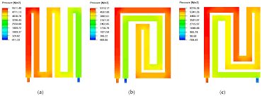
Temperature uniformity: A research team at Nanjing University of Information Science & Technology proposed an innovative liquid cold plate with serpentine channels, enhanced fins, and staggered turbulators. Experimental results showed that increasing coolant flow rate reduced the device peak temperature by approximately 22 K, with stable thermal performance over a certain flow range.
Trade‑off between cooling and pumping power: In a cold plate cooling system, increasing flow rate improves heat transfer but also increases pump power consumption non‑linearly. In electric vehicles, an extra 10 kPa pressure drop may cost several to tens of watts of pump power, which must be accounted for in the system power budget.
 5. Architecture Evolution: From Indirect Cooling to Embedded / DBC‑Integrated Liquid Cold Plate
In traditional cooling architectures, the IGBT module has a “chip – DBC – baseplate (Cu or AlSiC) – cold plate” multi‑layer stack, each layer adding thermal resistance. As noted, interface thermal resistance exceeds 60% of the total.
To overcome this, a disruptive architecture – embedded or DBC‑integrated liquid cold plate – has emerged. The idea is to integrate the DBC substrate directly into the cold plate, using high‑temperature processes to bond copper and ceramic (Al₂O₃ or AlN) into a monolithic structure. Coolant channels are placed directly under the chip, separated only by the DBC, dramatically shortening the heat conduction path.
Three major advantages: (1) eliminates the baseplate and external TIM, drastically reducing total thermal resistance; (2) channel resolution down to 0.3 mm, combined with high‑conductivity copper, achieves excellent isothermal performance; (3) supports high‑power‑density compact layouts and double‑sided component mounting. Key material parameters for this integrated scheme are shown in Table 2.
Table 2: Key material parameters for DBC‑integrated liquid cold plate (source: Electronics Cooling, 2025)
| Material Layer | Common Materials | Thermal Conductivity (W/m·K) | CTE (ppm/°C) |
|---|
| Semiconductor chip | SiC | 375 | 4.0 |
| Interconnect | AuSn solder / Ag sinter film | 50 / 200 | 15.9 / 18.9 |
| Ceramic insulation | Al₂O₃ / AlN | 35 / 170–200 | 6.5 / 4.2–5.7 |
| Cold plate body | Copper (Cu) | 360 | 16.7 |
This integration trend aligns with the market growth of direct‑cooled IGBT modules.
6. Material Selection and Coolant Technology
Cold plate material selection balances thermal conductivity, machinability, and cost. The most common choice is aluminum alloy 6063, with thermal conductivity around 180–230 W/(m·K). Copper offers ~401 W/(m·K) but density is three times that of aluminum, and cost is much higher, used only in high‑end applications with stringent cooling requirements.
The coolant is a critical carrier of heat transfer. A study published in Applied Thermal Engineering compared deionized water, purified water, 20% ethylene glycol‑water solution, and HFE7100. At Re = 1400, deionized water’s overall performance evaluation criterion (PEC) was 9.3%, 24.5%, and 163.9% higher than purified water, 20% ethylene glycol, and HFE7100, respectively. Re = 1400 (flow velocity ~0.5–0.6 m/s) was identified as the optimal operating range for low pressure drop. In practical systems, 50% ethylene glycol‑water mix is widely used, offering freeze protection and good thermal conductivity.
 7. Manufacturing Processes and Reliability Testing
The welding/sealing of a liquid cold plate directly affects long‑term reliability. For the four main types: tubed uses tube‑embedding + brazing or pressing; FSW uses friction stir welding; extruded uses extrusion + end sealing; brazed uses vacuum or atmosphere brazing. Vacuum brazing and FSW are the mainstream processes for high‑reliability cold plates.
Common welding defects include porosity, excessive spread, internal micro‑cracks, poor bonding, and flow channel blockage. For FSW and brazed cold plates, weld sealing and internal cleanliness must be carefully inspected.
Flatness is another key factor. According to Hertz contact theory, even macroscopically flat surfaces have microscopic peaks and valleys; actual contact area is much smaller than nominal area. Micron‑level flatness deviations can cause interface thermal resistance to rise dramatically. Typical acceptance criteria for cold plate cooling systems include:
Leak tightness: Helium leak test, leakage ≤ 1×10⁻⁶ Pa·m³/s or ≤ 0.05 mL/min @ 0.5–2.0 MPa
Pressure resistance: Hydraulic burst test ≥ 3× working pressure (normally ≥ 3.0 MPa)
Flatness: ≤ 0.05 mm per 100 mm (overall ≤ 0.1 mm)
Cleanliness: Particles ≤ 10 mg/m²
8. Value of Liquid Cold Plates in IGBT Application Fields
Electric vehicles: The liquid cooling plate handles heat from the traction inverter, directly affecting motor power output. SiC modules have 2‑3 times the power density of traditional IGBTs; efficient tubed, FSW, or brazed liquid cold plates effectively eliminate local hot spots, improving EV range and reliability.
Wind and solar inverters: IGBT modules run under long‑term high load; the cooling system must have long life and low maintenance. Cold plates provide lower stable junction temperatures and smaller temperature swings, significantly improving reliability under harsh conditions.
Rail transit: Electrification increases cooling demand; active liquid cooling (pump‑driven) provides more precise temperature control than natural convection or forced air cooling, enhancing reliability in extreme environments.
(Similar cooling plates for electronics are also used in cpu cooling plate for high‑performance processors, battery liquid cold plate for EV battery packs, and insulated cold plate designs for high‑voltage isolation.)
9. Market Outlook and Technology Trends
According to QYResearch, the global IGBT heatsink substrate market reached 720 million in 2024 and isexpected to reach 1.165 billion by 2031, with a CAGR of 7.7%. Within this growth, liquid cold plates – especially brazed and FSW types – are the key drivers. The 17.9% CAGR for direct‑liquid‑cooled IGBT modules is significantly higher than the overall 7.7% for IGBT substrates, indicating rapid penetration of liquid cooling technology.
An advanced concept, the multi‑nozzle jet impingement liquid cold plate (MJILCP) for 1000W TDP, presented at an IEEE conference, showed 14.3% lower thermal resistance and 19.3% lower pumping power compared to a conventional milled‑channel cooler cold plate. To achieve 0.0236°C/W thermal resistance, MJILCP required 48% less pump power.
Future evolution focuses on three directions:
Deep integration: from indirect cooling to embedded DBC integration, further reducing thermal resistance.
Intelligent design: AI‑assisted design, topology optimization, and additive manufacturing for custom flow channels (custom liquid cold plate, custom cold plates).
Multi‑scenario adaptation: customized solutions for 800V high‑voltage platforms, high altitude, etc., possibly including liquid nitrogen cold plate for extreme cooling needs.
As local manufacturing advances and the new energy revolution deepens, liquid cold plates will evolve from auxiliary components to core enablers of power density and reliability in IGBTs and wider power electronics.


