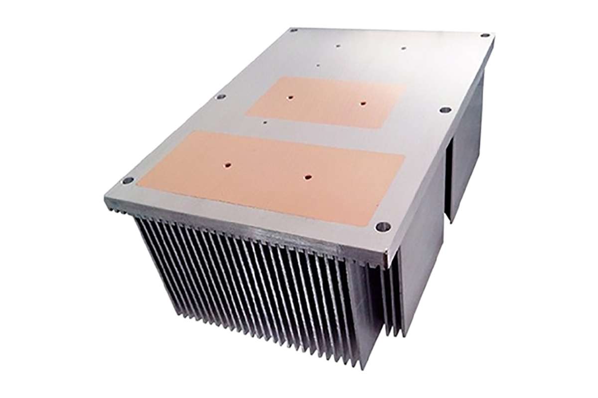
A heat sink is a thermal management component designed to dissipate heat from electronic devices into the surrounding environment. In Heat Sinks for electronics, heat is transferred through conduction from the heat source (such as a CPU or power module) into the heat sink base, then dispersed via heat sink fins through convection and radiation.
Understanding what is a heat sink, how heat sinks work, and how heat sinks are made is essential when selecting solutions such as aluminum heat sinks, copper heat sinks, liquid cooled heat sinks, or custom heatsinks for industrial and electronic applications.
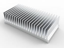
Among all manufacturing methods, CNC machined heat sinks offer the highest design freedom and precision, making them ideal for complex, high-performance, and low-volume applications where extruded heat sinks or heat sink extrusion cannot meet design requirements.
1. Raw Material Management Stage
1.1 Metal Billet Preparation
Material Selection
High thermal conductivity metals and composites are selected according to thermal and mechanical requirements:
Aluminum alloys: AA6061-T6 / AA6063-T5 / T651
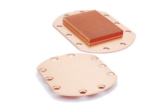
Copper alloys: C1100 / C1020
Composite materials: AlSiC, CuW
These materials are commonly used in aluminum heatsinks, copper heat sinks, and high-end industrial heat sink solutions.
Material Certification & Verification
Physical Property Testing
Thermal conductivity:
Aluminum ≥ 180 W/m·K
Copper ≥ 380 W/m·K
Hardness:
6061-T6: HB 95–100
6063-T5: HB 75–85
Tensile strength:
6061-T6 ≥ 290 MPa
6063-T5 ≥ 175 MPa
Billet Pre-Treatment
Stress relief (if required): 300°C × 2 hours, furnace cooling
Surface flatness check: ≤ 0.1 mm / 100 mm
Dimensional tolerance: ±0.5 mm (L × W × H)
1.2 Auxiliary Materials Preparation
Cutting tools:
Coolant systems:
Fixture materials:
2. Process Design and CAM Programming Stage
2.1 Machining Strategy Development
Process Route Planning
Rough machining: High-speed milling (80–90% material removal)
Semi-finishing: Contour machining with 0.1–0.2 mm allowance
Finishing: Precision machining to final dimensions
Toolpath Optimization
Contour machining: Step-over 0.5–2.0 mm
Parallel toolpaths: 30–70% tool diameter
Spiral toolpaths: Reduced tool entry impact
Deformation Control Strategies
2.2 CAM Programming
3D Model Processing
Model repair and simplification
Machining allowance setup:
Roughing: 0.3–0.5 mm
Finishing: 0–0.05 mm
Feature-based machining region segmentation
Toolpath Generation
Post-Processing & Simulation
NC code generation for specific CNC systems
Collision and travel verification
Machining time estimation (±10%)
3. Machining Preparation Stage
3.1 CNC Machine Setup
Machine Selection
3-axis vertical machining centers: Standard CNC machined heat sinks
4-axis / 5-axis CNC: Complex curved surfaces
High-speed machining centers: Spindle ≥ 12,000 rpm for thin fins
Machine Accuracy Verification
3.2 Fixture System Design
Clamping Force Control
Hydraulic clamping: 0.5–1.0 MPa
Pneumatic clamping: 0.4–0.6 MPa
Mechanical clamping: Torque controlled to ±0.1 Nm
4.1 Rough Machining
Workpiece alignment using edge finders (±0.01 mm)
Coordinate systems: G54–G59
Primary datum surface machining (flatness ≤ 0.02 mm)
Rough Cutting Parameters
Spindle speed: 8000–12,000 rpm
Feed rate: 1500–3000 mm/min
Depth of cut: 2–5 mm
Step-over: 60–70% tool diameter
Process Monitoring
4.2 Semi-Finishing
In-Process Control
4.3 Finishing (Critical Process)
Heat Sink Fin Machining
Thin fin processing using φ1–φ3 mm end mills
Spindle speed: 18,000–24,000 rpm
Feed rate: 300–800 mm/min
High-pressure internal coolant (≥70 bar)
Anti-Vibration Measures
Mounting Surface Machining
Face milling (φ40–φ80 mm cutters)
Surface roughness: Ra ≤ 0.8 μm
Flatness: ≤ 0.03 mm / 100 mm
Hole Machining
Special Structures
T-slots and profiled grooves
5-axis curved surface machining
Micro-structure machining (φ0.1–φ0.5 mm tools)
4.4 Advanced Machining Technologies
5. In-Process Quality Control
5.1 Online Inspection
Touch probes for alignment and dimensional inspection
Automatic tool compensation
Laser scanning for surface profiles
Vision systems for defect detection
5.2 Process Parameter Monitoring
6. Critical-to-Quality (CTQ) Control Points
| Stage | Parameter | Method | Standard |
|---|
| Raw Material | Thermal Conductivity | Laser Tester | ≥180 W/m·K |
| Machining | Spindle Runout | Dial Indicator | ≤0.003 mm |
| Dimensional | Mounting Flatness | Granite Plate | ≤0.03 mm/100 mm |
| Surface | Roughness | Roughness Tester | Ra ≤0.8 μm |
| Thermal | Thermal Resistance | Test Bench | ≤ Design +10% |
| Reliability | Salt Spray | Test Chamber | ≥96 hours |
7. Process Capability and Lead Time
Total Lead Time: 18–31 working days
Capacity:
8. Process Characteristics and Advantages
Technical Advantages
Extremely high design freedom
Micron-level precision
Suitable for custom heatsink solutions
Ideal for CPU heatsink, CPU heatsink fan, heatsink fan, heat sink with fan, and liquid cooled heat sink designs
Process Limitations
Recommended Applications
Prototypes and validation
Small-batch, high-value products
Complex geometry heat sinks
High-performance industrial heat sinks
Not recommended for:
High-volume standardized products
Cost-sensitive applications
Simple extruded heat sink designs
This CNC machined heat sink manufacturing process is optimized for high-precision, complex, and low-volume heat sink production. By combining optimized machining strategies, strict process control, and advanced inspection methods, heat sink manufacturers can achieve superior thermal performance, dimensional accuracy, and long-term reliability. The process can be flexibly adjusted to balance performance and cost according to specific application requirements.