

A water cooling plate transfers heat from an electronic component into circulating liquid. In an embedded tube construction, coolant follows a defined path through metal tubing positioned inside a conductive base.
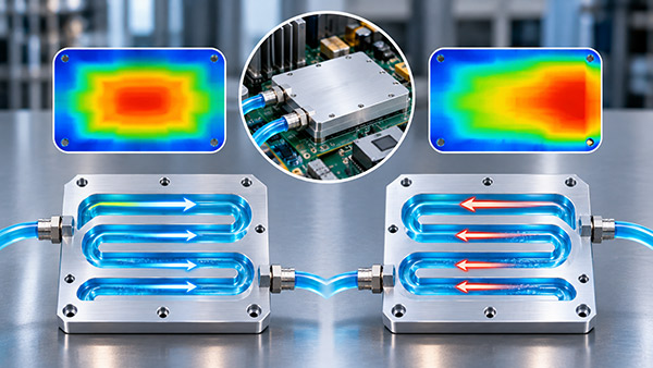
When integrating the plate into an OEM system, engineers sometimes ask whether the inlet and outlet can be exchanged without affecting performance.
The answer depends on the cold plate's internal construction, heat-source arrangement, operating conditions, and any direction-dependent components in the coolant circuit.
How Does Flow Direction Affect Cooling?
As coolant moves through the cold plate, it absorbs energy from the heat-generating components.
The coolant temperature generally increases along the flow path when the plate is removing heat.
Therefore, the region near the designated inlet may be exposed to cooler liquid than regions further downstream.
For a plate carrying several heat sources, reversing the coolant direction can change which components are cooled by the lowest-temperature fluid.
1. Consider Heat Source Locations
Suppose a cooling plate supports three power modules with different heat loads.
If the module with the strictest temperature limit is positioned near the coolant inlet, it may receive a thermal advantage from the lower local fluid temperature.
Reversing the flow could place that module closer to the warmer downstream coolant.
However, the effect cannot be predicted from component order alone. Base conduction, heat spreading, flow rate, and tube geometry also contribute to the final temperature distribution.
2. Understand Coolant Temperature Rise
A simplified energy balance for a single-phase liquid cooling circuit is:
Q = m × Cp × ΔT
Where:
Q is the heat transferred into the coolant.
m is the coolant mass flow rate.
Cp is the specific heat capacity.
ΔT is the bulk coolant temperature rise.
For example, if a cold plate transfers 300 W into water flowing at approximately 3 L/min, the estimated temperature rise is:
ΔT ≈ 300 / (0.05 × 4180) ≈ 1.44°C
This calculation uses an approximate water density of 1 kg/L and constant fluid properties.
The result describes the overall bulk coolant temperature increase, not the temperature of an individual electronic component.
3. Can Flow Reversal Change Pressure Drop?
For a simple continuous tube with no direction-dependent features, hydraulic resistance may be similar in both directions at the same flow rate.
However, this should not be assumed for every cooling assembly.
Directional fittings, valves, manifolds, local passage geometry, or other flow-control elements can create different operating conditions.
The complete circuit should be reviewed before reversing the designed flow direction.
4. What About Serpentine Tube Routing?
A serpentine embedded tube follows a continuous path beneath the cooling surface.
The orientation of that path relative to the heat sources influences where coolant reaches each region.
During design, engineers can consider whether the most temperature-sensitive modules should be positioned near the coolant inlet.
For applications with a nearly uniform distributed heat load, reversing the flow may have a smaller effect on the maximum component temperature.
The actual difference must be determined from analysis or representative testing.
Flow Direction Design Comparison
| Design Condition | Potential Effect of Flow Reversal | Recommended Review |
|---|---|---|
| One distributed heat source | May produce limited change in some designs | Compare plate temperature distribution |
| Multiple unequal heat sources | May alter critical module temperatures | Evaluate each component's thermal margin |
| Serpentine tubing | Changes order of coolant exposure | Review tube route and module positions |
| Directional valves or fittings | May affect hydraulic function | Verify permitted flow direction |
| Complex manifold | May change flow distribution | Analyze and test full hydraulic network |
How to Test Both Flow Directions
If the design must support reversible connections, the cooling plate should be tested under the relevant operating conditions in both directions.
Useful measurements include:
Coolant inlet temperature.
Coolant outlet temperature.
Actual coolant flow rate.
Pressure drop across the plate.
Critical component temperatures.
Surface temperature distribution.
Operation of any direction-dependent components.
Testing should use the same heat loads, coolant properties, and mounting conditions wherever a direct comparison is intended.
Should the Inlet and Outlet Be Marked?
Where the design has a required flow direction, the drawing and assembly documentation should identify the inlet and outlet clearly.
This may be done using part markings, installation instructions, or controlled connection identification.
For a direction-insensitive design, the supplier and equipment integrator should still agree on the permitted installation arrangements.
Custom Water Cooling Plate Design with KINGKA
KINGKA provides custom water cooling plate manufacturing with embedded metal tubing and application-specific connection layouts.
OEM engineers can submit heat-source locations, coolant flow requirements, inlet and outlet positions, and mounting drawings to discuss tube routing and manufacturing feasibility.
Optimize Your Water Cooling Plate Layout
Need an embedded tube cold plate with customized coolant routing and connection positions? Share your design requirements with KINGKA.
Explore KINGKA Water Cooling Plate SolutionsFrequently Asked Questions
Can the inlet and outlet of a water cooling plate be exchanged?
Possibly, but compatibility depends on the internal tube path, temperature requirements, and direction-dependent circuit components.
Does reversing water flow always change component temperature?
No. The effect depends on heat-source locations, fluid temperature rise, and the complete thermal design.
Can flow direction affect coolant pressure drop?
Yes, particularly when the system contains directional or asymmetric hydraulic features.
Should a custom water cooling plate show flow direction on its drawing?
Yes, when direction affects installation, thermal performance, or system operation. The documentation should define the approved connections.