

A skived heatsink may provide a large cooling surface within a compact structure, but its actual thermal performance cannot be determined from fin count or nominal material conductivity alone.
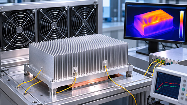
Airflow, mounting contact, heat source dimensions and the surrounding enclosure can all affect operating temperature.
For OEM electronics, representative prototype testing is an important step in determining whether a skived fin heat sink can maintain the required temperature under intended working conditions.
1. Why Thermal Testing Is Necessary
Heat sink performance is often discussed using thermal resistance or maximum heat dissipation capacity.
However, a published thermal resistance value may have been measured under a specific airflow rate, heat source configuration or laboratory setup.
The same heat sink may perform differently when installed inside a compact electronics enclosure.
For example, an enclosure may restrict the air reaching the fins or allow some airflow to bypass the cooling channels.
Therefore, prototype tests should represent the intended system as closely as reasonably practical.
2. Define the Heat Load Before Testing
The first step is to identify the thermal power that must be removed from the device.
For electronic systems, electrical input power is not always identical to the heat transferred into a particular heat sink.
Engineers should determine the relevant heat load based on the equipment's actual thermal behavior.
Depending on the application, it may be necessary to evaluate:
Continuous operating power.
Peak or short-duration heat loads.
Different operating modes.
Power distribution across multiple components.
Expected ambient and inlet air temperatures.
Clear test conditions make the results more useful for design approval.
3. How to Measure Heat Sink Thermal Resistance
A common steady-state thermal performance indicator is the temperature difference between a defined heat sink location and the cooling air, divided by the heat transferred through the heat sink.
Where:
Rθ = base-to-inlet-air thermal resistance, in °C/W.
Tbase = temperature at the defined heat sink base measurement point.
Tair,inlet = inlet air temperature.
Q = heat transferred through the heat sink, in watts.
This simplified relationship is useful when the relevant temperatures and heat flow are known under steady-state conditions.
If the measurement uses device junction temperature instead of base temperature, the reported resistance describes a different thermal path and should not be directly compared without accounting for that difference.
4. Select Appropriate Temperature Measurement Points
Temperature measurements should be taken at locations that reflect the engineering objective.
Possible measurement locations include the electronic heat source, the heat sink base, selected fin regions and the cooling air inlet.
Sensor placement matters because different positions on a heat sink can have different temperatures.
The mounting method for a sensor should also be considered to avoid disturbing the thermal interface or cooling airflow.
When comparing different prototypes, use consistent measurement locations and sensor installation methods.
5. Evaluate the Actual Fan and Airflow Conditions
Forced-air skived heatsinks depend on air moving through the fin passages.
However, a fan's advertised free-air airflow rating does not necessarily represent the airflow delivered after it is installed with a heat sink, duct or enclosure.
The actual operating point depends on the interaction between fan performance and system flow resistance.
During testing, engineers should consider the fan speed, configuration, airflow direction and any surrounding structures that influence air movement.
If the product uses multiple fan-speed settings, the heat sink may need to be evaluated at more than one operating condition.
6. Why the Thermal Interface Material Matters
Heat must pass from the electronic device into the heat sink base.
The thermal interface material, mounting pressure and contact surface condition can affect this transfer.
If two heat sink prototypes are tested using different interface materials or mounting conditions, differences in measured temperature may not be caused by the fin designs alone.
Therefore, comparative testing should control the interface configuration as carefully as practical.
7. Wait for Appropriate Thermal Stabilization
For steady-state thermal resistance testing, temperatures should be allowed to approach a stable condition before the final readings are recorded.
The required stabilization period depends on the thermal mass, heat load and complete test setup.
There is no single stabilization time suitable for every heatsink.
For equipment subject to short power bursts, additional transient testing may be needed because steady-state results do not fully describe temperature changes during rapid load transitions.
8. What Should a Thermal Test Report Include?
A useful prototype test report should document enough information for the results to be understood or reproduced.
Heat sink part number and revision.
Material and relevant fin geometry.
Heat source configuration.
Applied heat load.
Thermal interface material and mounting method.
Fan, airflow or natural-convection arrangement.
Ambient or inlet air temperature.
Temperature sensor locations.
Measured results and calculation method.
Any deviations from the planned test conditions.
This level of documentation is particularly helpful when comparing multiple candidate designs or repeating tests after a product revision.
9. How to Compare Two Skived Fin Designs
When evaluating different Skived Fin Heat Sinks, engineers should avoid changing several test conditions simultaneously without recording those changes.
For example, if a new heat sink has different fin pitch and a different fan, an improved component temperature cannot be attributed solely to the fin geometry.
Where practical, controlled comparisons should isolate relevant design variables.
The final selection should reflect thermal performance together with manufacturing feasibility, assembly, acoustic performance, reliability and cost.
10. Custom Skived Heatsink Development at KINGKA
KINGKA supplies copper and aluminum skived heatsinks for custom thermal management applications.
Engineers developing a new cooling assembly can review KINGKA's skived fin heat sink manufacturing options and provide thermal loads, enclosure constraints and engineering drawings for technical evaluation.
Where application-specific performance is critical, prototype qualification should be completed using representative system conditions.
Frequently Asked Questions
Can a skived fin heat sink be evaluated without a fan?
Yes, for a natural-convection design. However, results from natural-convection testing should not be treated as equivalent to forced-air performance.
Does lower thermal resistance always mean a better heatsink?
Under equivalent conditions, lower thermal resistance indicates better heat removal relative to the chosen temperature reference. However, size, weight, airflow requirements, acoustic behavior and cost may also influence the overall selection.
Why do thermal results differ between laboratory and installed conditions?
Differences in airflow, mounting contact, temperature measurement and surrounding geometry can change the operating temperature.
Reliable thermal validation requires more than reading a nominal heat sink specification.
By testing the complete skived heatsink assembly with representative heat loads, mounting conditions and airflow, OEM engineers can make more informed decisions before approving a custom cooling solution for production.
Need to Validate a Custom Skived Heatsink Design?
Share your thermal requirements, drawings and operating conditions to discuss a suitable custom manufacturing solution.
Explore KINGKA Skived Fin Heat Sinks