

A skived heatsink can provide a high number of thin metal fins within a compact cooling footprint. However, increasing fin density does not always improve the temperature of an electronic component.
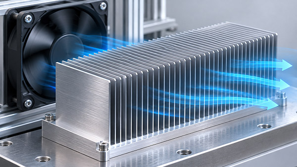
In forced-air applications, fin pitch influences both the available heat transfer surface and the resistance encountered by the cooling air. An effective design must balance these factors with the fan's actual operating capability.
What Is Fin Pitch in a Skiving heat sink?
Fin pitch is the center-to-center distance between adjacent fins in a regular fin array.
It is different from the open air gap between the fins.
For parallel fins with uniform thickness, a simplified relationship is:
Open Gap = Fin Pitch - Fin Thickness
For example, consider a hypothetical skived fin array with a 1.0 mm pitch and a 0.3 mm fin thickness.
The nominal gap is:
1.0 - 0.3 = 0.7 mm
This calculation assumes parallel fins and consistent geometry. Actual clearances can vary due to fin tilt, forming conditions and manufacturing tolerances.
1. More Fins Mean More Potential Surface Area
Reducing fin pitch allows more fins to fit within a given width, provided that the manufacturing process can produce the specified geometry.
Additional fins increase the available surface area for heat transfer.
However, the full area does not necessarily operate at the same temperature or with the same local heat transfer coefficient.
The benefit also depends on fin height, thickness, conductivity and the movement of air between the fins.
2. Narrower Channels Increase Airflow Challenges
As the open channel gap decreases, airflow resistance may increase for a given flow condition.
This can reduce the airflow delivered by a fan once the heat sink is installed in the complete equipment.
If the cooling air cannot move adequately through the narrow channels, the extra metal surface area may provide less benefit than expected.
Therefore, the finest possible pitch is not automatically the optimum choice.
3. Consider Fin Height and Channel Length
Fin pitch should not be evaluated independently of fin height and length.
Tall, closely spaced fins can create a large surface area, but the airflow must travel through the resulting passages.
Longer flow paths generally introduce additional frictional resistance under comparable conditions.
The effective thermal performance depends on how these geometric factors interact with the selected fan or blower.
4. Match the Skived Fin Array to the Fan
A cooling fan is characterized by a relationship between airflow and static pressure.
The actual airflow is determined by the interaction between the fan curve and the resistance of the installed system.
The airflow value printed on a fan specification sheet may represent a different operating condition from the final electronics enclosure.
For dense skived fins, it is useful to review the system pressure drop and fan performance together.
Changing the fin pitch may shift the system resistance curve and change the delivered airflow.
5. Avoid Excessive Air Bypass
Air may flow around a fin array instead of traveling through its channels if the surrounding enclosure provides an easier path.
Such bypass flow can reduce the effectiveness of a dense skived heatsink.
Depending on the system, suitable ducting or airflow guides may help direct air through the intended cooling region.
However, added ducts and covers can also introduce additional pressure losses.
The complete assembly should be tested rather than assuming that a tightly enclosed fin array always performs better.
Skived Fin Pitch Design Considerations
| Parameter | Thermal or Hydraulic Influence | Manufacturing Concern |
|---|---|---|
| Fin pitch | Changes fin count and channel density | Skiving process capability |
| Fin thickness | Changes conduction and open gap | Fin formation and stability |
| Fin height | Changes cooling area and fin efficiency | Height variation and deformation |
| Flow length | Changes channel resistance | Overall part dimensions |
| Fan performance | Determines actual delivered airflow | System integration |
| Enclosure geometry | Affects bypass and pressure loss | Assembly clearances |
How to Validate the Optimum Pitch
A practical development process may compare several candidate fin pitches using the intended fan and enclosure configuration.
Each candidate should be evaluated at the relevant heat load and air inlet temperature.
Useful measurements include component temperature, inlet and outlet air temperature, actual flow conditions and pressure difference across the cooling path.
For a fair comparison, the test should document changes in fin count, thickness, height and geometry rather than treating pitch as the only variable.
Custom Skived Heatsink Manufacturing
KINGKA provides custom skived heatsink manufacturing in aluminum and copper for high-density electronic cooling applications.
OEM customers should specify fin pitch, thickness, height, base dimensions and cooling requirements to support a manufacturing feasibility review.
Optimize a High-Density skiving heat sink
Developing a compact forced-air cooling assembly? Submit your target thermal performance, fan information and fin geometry to KINGKA.
View Custom Skived Fin Heat SinksFrequently Asked Questions
Is fin pitch the same as fin spacing?
Not always. Fin pitch is normally the center-to-center distance, while the open gap is the clear distance between adjacent fin surfaces.
Does a smaller pitch always improve cooling?
No. Smaller pitch can increase surface area but may also increase airflow resistance.
Can a skived heatsink use very thin fins?
Yes. The skiving process supports thin integral fins, subject to material, height, width and manufacturing constraints.
Should fin pitch be confirmed during prototype testing?
Yes. Actual thermal and airflow performance should be verified under representative equipment conditions.