

A skived fin heat sink can provide a large cooling surface within a relatively compact footprint. However, its thin and closely spaced fins can create practical challenges during installation, especially when the heat sink must fit around circuit boards, connectors and other mechanical components.
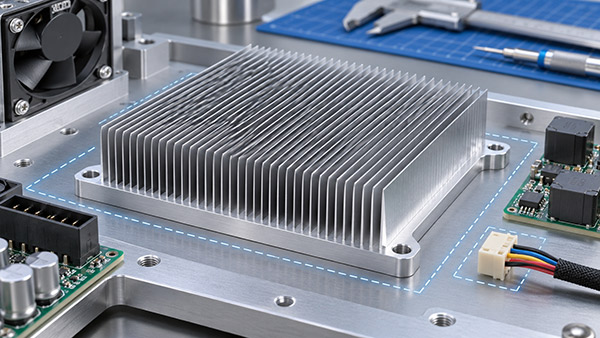
For OEM electronics, thermal performance is only one part of the design. Engineers also need to ensure that the heatsink can be mounted safely, inspected and assembled without damaging the fin array.
Planning mounting zones and component clearances early can reduce the need for costly design changes after the first prototype is manufactured.
1. Why Skived Fin Arrays Need Assembly Clearance
Skiving can produce thin fins arranged closely together to increase the available cooling area.
While this geometry is useful for compact thermal designs, the fins may be vulnerable to bending if excessive force is applied during assembly.
Nearby structures may also interfere with the fin array if the heat sink's occupied envelope is not clearly defined.
Therefore, mechanical drawings should describe both the base dimensions and the space occupied by the complete fin structure.
2. Plan Mounting Holes Before Finalizing Fin Layout
Some Custom Heatsinks use screws passing through mounting holes in the base. Others use brackets, spring clips or dedicated mounting hardware.
Each approach creates different requirements for assembly access.
For screw-mounted parts, engineers should consider:
Fastener diameter and head dimensions.
Access for assembly tools.
Distance between fasteners and thin fins.
Local base stiffness around the mounting feature.
Required pressure on the thermal interface.
Whether a mounting flange or fin-free region is necessary.
Mounting holes should not be added after the fin design is approved without assessing the effect on geometry and manufacturing operations.
3. What Is a Fin Keep-Out Zone?
A fin keep-out zone is a region reserved for mechanical access or other required features rather than occupied by cooling fins.
For example, a designer may reserve a narrow area beside the fin array so a fastening tool can reach a mounting screw.
This can help prevent direct contact between the tool and the delicate fins.
However, removing fins also changes the available cooling area. The final design should balance assembly access and thermal performance.
4. Account for Tolerance Accumulation
Nominal CAD dimensions do not represent every possible manufactured or assembled condition.
Fin dimensions, base dimensions, mounting positions and neighboring enclosure components all have tolerances.
When several parts are assembled, their variations can accumulate.
Therefore, clearances should be reviewed using the relevant tolerance conditions rather than checking only the nominal model.
Where electrical components are nearby, required insulation and electrical clearance constraints must also be considered independently of mechanical fit.
5. Avoid Contact Between Fins and Nearby Components
A dense fin array may sit close to a fan housing, connector, PCB edge or equipment cover.
Unintended contact can deform fins or place unwanted loads on the heat sink assembly.
Engineers should identify the complete installed envelope, including expected fin angle and permitted geometric variation.
Clearance requirements may also need to account for vibration, thermal movement and service access.
6. Combine CNC Machining with Skiving
Custom skived heatsinks may require additional machining operations for mounting features, contact faces or component interfaces.
The manufacturing sequence should be evaluated because machining after fin formation may introduce handling or fixturing challenges.
Likewise, the method used to hold the workpiece should avoid damaging surfaces needed for later operations.
Manufacturing teams should review whether the proposed feature arrangement is practical for the selected process.
7. Check the Thermal Interface During Assembly
A suitable fin design cannot compensate for poor contact between the electronic device and the heat sink base.
The assembly should maintain the intended thermal interface material thickness and mounting conditions.
Uneven mechanical loading can influence contact quality, especially when the base must span multiple mounting points.
For this reason, thermal interface verification and mechanical fit checks should be considered together during prototype testing.
8. Assembly Review Checklist
Before releasing a custom skived heatsink drawing, confirm:
Fin array dimensions and occupied envelope.
Mounting-hole positions and required hardware.
Tool access and assembly sequence.
Specified fin-free or keep-out regions.
Base contact surface and interface requirements.
Clearance from nearby components and enclosure walls.
Relevant dimensional and electrical safety requirements.
These checks can help identify conflicts before manufacturing begins.
9. Custom OEM Skived Heat Sink Manufacturing
KINGKA provides custom skived heat sinks in aluminum and copper for electronics thermal management.
OEM teams can submit a complete assembly model when discussing skived fin heat sink manufacturing, allowing fin geometry, base machining and mounting constraints to be considered together.
Frequently Asked Questions
Can mounting holes be machined into a skived heatsink?
Yes, depending on the geometry and available machining regions. The location and manufacturing sequence should be reviewed.
Is a fin keep-out zone always necessary?
No. Its need depends on the mounting method, tool access and surrounding assembly.
Should mounting clearance be checked before prototype testing?
Yes. Mechanical fit, assembly access and thermal contact should be reviewed before approving a production design.
Effective Skived Fin Heat Sink design requires both thermal engineering and practical assembly planning.
By reserving suitable mounting zones, defining clearances and evaluating CNC machining requirements early, OEM engineers can reduce installation risks while maintaining an appropriate cooling design.
Need an OEM Skived Heat Sink with Custom Mounting Features?
Provide your heat sink drawing, component layout and installation requirements for a manufacturing feasibility review.
View Custom Skived Fin Heat Sinks