

Airflow direction is an important consideration when choosing a pin fin heat sink or a Skived Fin Heat Sink for electronic equipment. Although both designs increase the available cooling surface area, their fin structures interact with airflow in different ways.
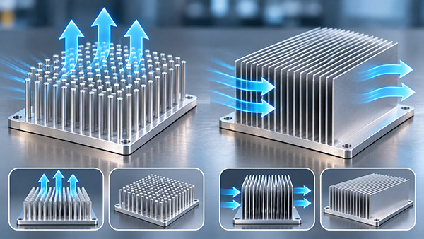
Pin fin structures contain individual protruding fins, while conventional skived fin heat sinks use thin, closely spaced plate fins formed directly from a metal base. Understanding this geometric difference helps OEM engineers select cooling hardware for the actual airflow conditions.
What Is a Pin Fin Heat Sink?
A pin fin heat sink contains an array of individual posts extending from a conductive base. The pins may be round, square, or another suitable geometry.
These structures can be produced using processes such as cold forging, casting, or machining, depending on the material and design.
A pin heat sink is often considered when the cooling air may approach the structure from different directions.
However, the actual performance depends on pin diameter, spacing, height, airflow velocity, and the surrounding enclosure.
What Is a Skived Fin Heat Sink?
A skived fin heat sink is manufactured by slicing and raising thin fins from a solid block of aluminum or copper.
The fins remain integral with the base, eliminating a separate bonded or soldered attachment interface.
Conventional skived heatsinks typically use parallel plate-fin channels.
This arrangement can offer a large surface area within a compact footprint, particularly when the airflow is directed along the fin channels.
1. Airflow Parallel to the Fins
When air enters the open end of a skived fin array, it can travel along the channels between adjacent fins.
The resulting cooling behavior depends on the available flow, channel dimensions, and fin length.
A dense fin array may provide substantial surface area, but it also introduces flow resistance.
For a pin fin structure, air travels around individual pins. The pattern of flow separation and mixing depends on the arrangement of the posts.
Neither design can be declared superior without considering the full operating conditions.
2. Airflow Across the Fins
If air approaches a conventional parallel plate-fin heat sink from the side, the fin arrangement may obstruct the direct flow path.
Depending on the enclosure, air may be redirected or bypass parts of the cooling array.
A pin fin heat sink can provide alternative flow paths between individual pins, which may be useful when incoming air direction varies.
However, the pin pattern can still produce significant pressure losses.
3. Natural Convection
Passive cooling relies on the movement of air caused by temperature differences.
The orientation of plate fins can affect the ability of warm air to escape.
A pin fin design may be less sensitive to certain airflow directions, but it is not automatically the better passive cooling solution.
Fin density, installation orientation, obstruction clearance, and available cooling area must also be considered.
4. Pressure Drop and Fan Performance
For forced-air systems, the heat sink's flow resistance affects the actual fan operating point.
A structure with more exposed surface area may not deliver better thermal performance if the fan cannot supply sufficient airflow through it.
Engineers should compare thermal resistance and pressure loss together rather than relying only on the total number of fins.
Pin Fin vs Skived Fin Comparison
| Design Factor | Pin Fin Heat Sink | Skived Fin Heat Sink |
|---|---|---|
| Fin structure | Individual posts | Continuous thin plate fins |
| Typical manufacturing | Forging, casting or machining | Precision metal skiving |
| Airflow direction | Can accommodate multiple approach directions | Often favors flow along fin channels |
| Fin-to-base joint | Depends on manufacturing method | Integral for a one-piece skived design |
| Pressure drop | Depends on pin pattern and flow | Depends on channel spacing and length |
| Best evaluation method | Test at intended installation conditions | Test at intended installation conditions |
How Should OEM Engineers Compare the Two Designs?
A meaningful comparison should use representative heat loads, installation space, inlet air temperature, and fan conditions.
If airflow direction may change, engineers can compare performance with air approaching from different orientations.
For example, a test may examine airflow parallel to the plate fins and then examine the effect of a rotated installation.
Temperature measurements should be taken at the relevant electronic components, not only at the fin tips.
Custom Skived Fin Heat Sink Manufacturing
For applications requiring dense, integral plate fins, KINGKA provides custom skived fin heat sink manufacturing using aluminum and copper materials.
OEM customers can submit heat loads, installation dimensions, fin requirements and airflow conditions for manufacturing review.
Find the Right Fin Structure for Your Equipment
Need a custom thin-fin cooling solution for industrial electronics? Explore KINGKA's skived fin designs and discuss your engineering requirements.
Explore KINGKA Skived Fin Heat SinksFrequently Asked Questions
Is a pin fin heat sink the same as a skived fin heat sink?
No. A conventional pin fin heat sink uses individual posts, while a conventional skived fin heat sink uses thin plate fins formed from the base metal.
Is a pin heat sink better for multidirectional airflow?
It may be advantageous in certain arrangements, but the result depends on geometry, airflow resistance and installation conditions.
Can skived fin heat sinks be used with forced-air cooling?
Yes. Dense skived fin arrays can be suitable for forced-air applications when the fan and fin channels are appropriately matched.
Should heat sink selection be based on surface area alone?
No. Heat spreading, fin efficiency, airflow and pressure loss also affect the operating temperature of electronic components.