

An FSW water cooling plate uses internal machined passages sealed by friction stir welding to transfer heat into circulating coolant. Although channel geometry is important, the inlet and outlet connections are equally critical to the finished cooling system.
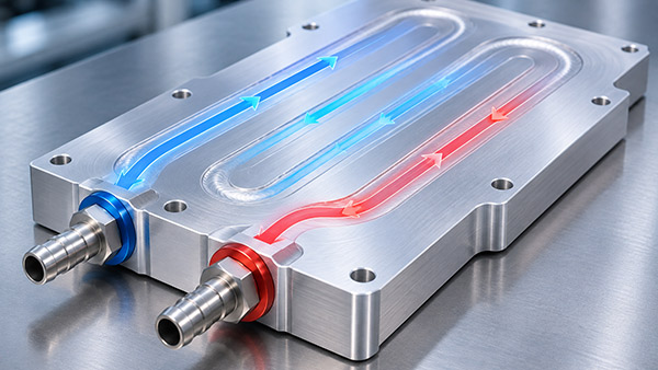
A poorly positioned port can create mechanical interference, complicate sealing, or increase pressure losses. Connection design must also account for the material surrounding the machined channel and the location of the FSW weld.
For OEM engineers, inlet and outlet requirements should be defined before releasing the final water cooling plate drawing.
1. Choose Suitable Port Locations
Inlet and outlet placement affects the installation of hoses, manifolds, fittings, and other cooling circuit components.
A convenient port position on the cold plate drawing may become inaccessible when the plate is installed inside the final equipment.
Engineers should review the complete assembly, including nearby electrical components, mounting brackets, and available connection space.
Port locations should also support the intended internal coolant route without creating unnecessary restrictions.
2. Consider the Internal Channel Connection
An FSW cold plate normally contains machined passages that must connect to the external coolant circuit.
The port geometry should provide a suitable transition between the external fitting and the internal channel.
Sharp restrictions, unexpected changes in cross-sectional area, or poorly aligned openings can affect local pressure losses.
However, maximizing every passage diameter is not always necessary.
The appropriate dimensions depend on the total flow requirement, system pressure, and available plate geometry.
3. Maintain Clearance from the Welding Path
Port features may include threaded holes, bosses, sealing surfaces, or other machined details.
If these features are positioned too close to the FSW welding area, they may interfere with tool movement or reduce the remaining material available for the joint.
Similarly, excessive machining near a sealed channel can affect the pressure boundary.
The channel, port, and weld path should therefore be reviewed together.
A manufacturing feasibility review can help identify conflicts before the first prototype is produced.
4. Select the Correct Connection Standard
Fluid connections may use different thread and sealing arrangements.
For example, a design may specify a suitable straight-thread connection with a separate seal or another qualified fitting system.
The drawing should identify the exact thread standard and the intended sealing method.
Similar-looking fittings are not necessarily interchangeable.
Mixing incompatible thread types can damage the plate or create unreliable connections.
5. Design the Sealing Surface
The port's sealing surface must be compatible with the selected fitting.
Depending on the connection design, sealing may rely on a suitable O-ring, gasket, or another approved mechanism.
Critical characteristics can include surface condition, dimensions, alignment, and available material around the port.
The sealing method should be selected according to pressure, coolant compatibility, temperature, and mechanical requirements.
A threaded connection alone should not be assumed to provide a reliable fluid seal in every design.
6. Account for Hose and Fitting Loads
External hoses and fittings may apply forces or moments to the cold plate.
These loads can result from hose bending, assembly operations, vibration, or maintenance activities.
The port structure must have sufficient mechanical support for the intended connection.
Where appropriate, hose supports or external brackets may reduce unwanted loads on the plate.
Mounting and support requirements should be defined by the equipment designer.
7. Consider Filling, Air Removal, and Draining
The orientation of the cold plate within the cooling system can influence how air is removed during filling.
Trapped air may affect hydraulic behavior and thermal performance.
Depending on the application, port positions or additional circuit features may assist with filling and maintenance.
However, the correct design must consider the complete cooling loop rather than the cold plate alone.
FSW Water Cooling Plate Port Design Checklist
| Design Parameter | Key Requirement |
|---|---|
| Port location | Compatible with equipment installation |
| Port diameter | Suitable for required flow and connection geometry |
| Thread specification | Clearly defined standard and dimensions |
| Sealing method | Compatible with fitting, coolant and pressure |
| Distance from weld | Compatible with FSW tool access and joint structure |
| Mechanical support | Account for hose loads and installation forces |
| Assembly orientation | Consider filling, air removal and service access |
| Inspection | Verify dimensions and leakage requirements |
How Should Port Connections Be Tested?
After manufacturing, the completed plate should be inspected against the approved connection dimensions.
Relevant tests may include pressure integrity and leak testing with suitable temporary or production-representative fittings.
The test method must clearly identify whether the connection itself is included in the verification boundary.
A cold plate body that passes testing with temporary plugs does not automatically prove the reliability of every fitting used in the final equipment.
Custom FSW Water Cooling Plate Manufacturing
KINGKA provides custom FSW water cooling plate manufacturing for industrial electronics, power modules, and other liquid-cooled equipment.
Port locations, mounting features, and internal channel layouts can be reviewed according to customer drawings and operating requirements.
Customize an FSW Water Cooling Plate
Need customized inlet and outlet connections for an aluminum FSW cooling plate? Send KINGKA your 2D/3D drawings, coolant requirements, fitting specifications, and application details.
Explore KINGKA FSW Water Cooling PlatesFrequently Asked Questions
Can inlet and outlet positions be customized?
Yes, where the proposed positions are compatible with the channel layout, weld structure, and manufacturing requirements.
Can threaded ports be machined after friction stir welding?
Depending on the design and manufacturing sequence, post-weld port machining may be possible. The remaining wall thickness and sealing structure must be protected.
Do all FSW cold plates use the same port thread?
No. The thread and sealing arrangement should be specified according to the intended cooling system.
Should the fittings be included in leak testing?
When joint reliability is part of the acceptance requirement, the relevant production connection configuration should be included in appropriate qualification testing.