

A Liquid Cooling Plate may contain several internal channels arranged to remove heat from different areas of an electronic assembly. When these channels share common inlet and outlet manifolds, their individual flow rates may not be equal.
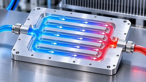
This matters because the total coolant flow entering the plate does not automatically reveal how much liquid reaches each cooling passage.
For FSW cold plates with multiple machined channels, internal flow distribution should be considered during design rather than assuming that every branch receives the same amount of coolant.
1. Why Use Multiple Internal Channels?
A multi-channel water cooling plate can provide several coolant paths across the plate's cooling area.
Such layouts may be considered when the device contains distributed heat sources or when a single long channel would create an undesirable hydraulic or temperature profile.
Parallel passages can potentially reduce the total hydraulic resistance compared with a single restrictive path, depending on their geometry.
However, adding parallel channels also introduces the need to distribute coolant appropriately.
2. How Does Coolant Choose Between Channels?
Within a connected hydraulic network, the flow through each branch depends on the pressure difference and the branch's hydraulic resistance.
A passage with lower resistance may carry more flow than a neighboring passage with higher resistance.
Differences may result from:
Channel length.
Hydraulic diameter and cross-section.
Number and geometry of bends.
Entrance and exit restrictions.
Local manifold pressure.
Manufacturing variation in the internal passages.
Even channels with identical nominal dimensions may receive different flow if the inlet manifold does not deliver similar pressure conditions to each branch.
3. Why Manifold Geometry Matters
An inlet manifold distributes coolant from the main connection into individual channels. An outlet manifold collects flow before it leaves the cold plate.
If the manifold geometry creates significant pressure variation along its length, some branches may receive more coolant than others.
For example, channels near the inlet may experience different pressure conditions from those farther along the manifold.
The actual distribution depends on the relative manifold and branch resistances, so the direction of the imbalance cannot be determined from channel location alone.
4. Does Uniform Flow Always Produce the Best Thermal Result?
Not necessarily.
A cold plate cooling several devices may have unequal heat loads across its surface.
If one module dissipates considerably more heat than another, an intentionally nonuniform flow allocation may be worth evaluating.
The goal should be to satisfy the temperature limits of all relevant components while maintaining acceptable pressure drop.
Uniform flow can be a useful design objective, but thermal performance should determine whether it is appropriate.
5. Design Methods for Improved Distribution
Depending on the manufacturing constraints, engineers may consider adjusting manifold geometry, channel dimensions or individual branch resistance.
Possible approaches include:
Changing the inlet manifold cross-section.
Evaluating different inlet and outlet arrangements.
Reducing unnecessary local restrictions.
Balancing branch lengths where practical.
Using suitable resistance features where justified.
Relocating coolant paths around critical heat sources.
Every change should be checked for its effect on the complete pressure-drop and thermal performance of the plate.
6. Manufacturing Considerations for FSW Construction
In a friction stir welded cold plate, internal channels are typically CNC-machined before the cover is welded into place.
This allows the channel layout to be designed around the heat source distribution, but the design must remain compatible with machining and welding requirements.
Complex manifold features may introduce additional demands on channel support, remaining wall thickness and weld accessibility.
For this reason, the CFD model and the manufacturing drawing should use geometry that can realistically be produced.
7. How to Evaluate Flow Distribution
Computational fluid dynamics can help estimate how coolant moves through the internal passages.
Depending on the model and project requirements, the analysis can examine pressure variation, branch flow rates and local thermal behavior.
For designs requiring stronger verification, representative prototype testing may be used to compare predicted temperatures and total hydraulic performance.
Direct measurement of individual branch flow is not always practical in a sealed plate. Alternative validation methods should therefore be selected according to the design and available test equipment.
8. Flow Distribution Design Checklist
| Design Element | Potential Issue | Review Objective |
|---|---|---|
| Inlet manifold | Uneven pressure distribution | Evaluate branch inlet conditions |
| Branch channels | Different hydraulic resistance | Check intended flow allocation |
| Outlet manifold | Uneven collection pressure | Review branch outlet conditions |
| Channel bends | Additional local losses | Compare practical routing options |
| Thermal loads | Localized hot spots | Confirm component temperatures |
| FSW joint regions | Manufacturing interference | Verify channel and weld feasibility |
9. Custom Multi-Channel Liquid Cooling Plates
KINGKA manufactures custom FSW cold plates using machined coolant passages and solid-state welding.
OEM engineers considering a custom liquid cooling plate can provide their heat-source layout, flow requirements and channel concepts for a manufacturing feasibility discussion.
For multi-channel designs, both thermal and hydraulic acceptance criteria should be defined before production approval.
Frequently Asked Questions
Do identical channels always receive identical flow?
No. Manifold pressure distribution and other hydraulic conditions can create unequal flow, even when channels have similar nominal dimensions.
Is higher flow always better for cold plate cooling?
No. Higher flow may improve heat transfer but can also increase pressure loss and pumping requirements.
Can CFD replace prototype testing?
CFD is useful for design evaluation, but its results depend on modeling assumptions. Physical validation may be required for critical applications.
Conclusion
Internal coolant distribution is an important design consideration for multi-channel FSW liquid cooling plates.
By evaluating manifold pressure, individual channel resistance and the actual thermal load distribution, engineers can develop more balanced and manufacturable cold plate designs.
Developing a Multi-Channel Cooling Plate?
Submit your heat-source map, proposed channel layout, flow conditions and engineering drawings for an FSW design review.
View KINGKA FSW Cold Plate Solutions