

A custom FSW Liquid Cold Plate combines CNC-machined coolant channels with a metal cover joined by friction stir welding. While channel geometry determines much of the hydraulic and thermal performance, the surrounding weld land is equally important for manufacturing feasibility and sealing integrity.
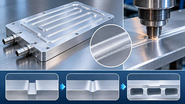
Engineers sometimes focus on placing coolant channels as close as possible to the heat source. However, an internal passage that approaches the welding path too closely may leave insufficient solid material to support the friction stir welding process.
For OEM manufacturers, weld land design should be considered during the initial cooling plate layout rather than after the channel geometry has been finalized.
What Is a Weld Land in an FSW cold plate?
A weld land is a region of solid material provided for the welding operation between the base and cover.
In a typical friction stir welding Liquid Cold Plate, a rotating tool travels along a defined joint path and plastically stirs the metal to form a solid-state joint.
The tool requires an appropriate material thickness, joint configuration, and mechanical support to achieve the intended weld.
If the tool path is placed too close to an internal cavity, the remaining material may not adequately support the process or satisfy the finished pressure requirements.
1. Establish the Coolant Channel Layout
The first design step is to identify the thermal requirements of the plate.
These include the number and location of heat sources, coolant inlet temperature, required flow rate, permitted pressure drop, and available plate dimensions.
Once a preliminary coolant channel layout is developed, engineers should identify where the cover needs to be joined to the base.
The channel design and welding path must be reviewed together.
It is generally more efficient to resolve weld access and material-support constraints before CNC programming and prototype production.
2. Provide Sufficient Material Around the Channel
The required solid material between a coolant channel and the weld path depends on several factors:
FSW tool shoulder and pin geometry.
Base and cover plate thickness.
Aluminum alloy and material condition.
Joint configuration.
Channel depth and wall geometry.
Tool positioning accuracy.
Operating pressure and structural loads.
Backing and fixturing arrangements.
There is no universal minimum weld land width suitable for every FSW liquid cold plate.
The final dimension should be agreed with the manufacturer based on the selected welding process and qualification requirements.
3. Consider the FSW Tool Path
A friction stir welding tool must be able to follow the intended joint without interfering with mounting features, raised bosses, or other mechanical obstacles.
Complex coolant channels may create a challenging weld path if the available joining area is narrow or discontinuous.
For some designs, modifying the cover geometry or moving a channel slightly may improve welding accessibility.
These changes should be reviewed for their effect on heat transfer and pressure drop.
4. Review Cover Plate Thickness
The cover plate contributes to the mechanical structure of the completed cold plate.
Its thickness must be compatible with the FSW tool and the required joint configuration.
A cover that is too thin for the selected process may be difficult to weld consistently.
An excessively thick cover may increase weight and alter the thermal conduction path.
Depending on the joint design, the cover may also need to withstand internal coolant pressure over unsupported channel regions.
5. Plan Weld Start and Stop Locations
FSW tool entry and exit conditions require attention.
Some conventional FSW processes can leave a tool exit feature or require special handling of the weld termination.
For a sealed cooling plate, the termination strategy must not create an unintended leakage path.
Possible solutions depend on the equipment, joint design, and available material.
The manufacturer should define the approved start, stop, and termination method before production.
FSW Weld Land Design Checklist
| Design Parameter | Potential Risk | Recommended Review |
|---|---|---|
| Weld land width | Insufficient material support | Confirm against qualified tool geometry |
| Channel-to-weld distance | Unintended channel deformation or leakage risk | Evaluate joint and channel cross-section |
| Cover thickness | Incompatible joint geometry | Review welding depth and pressure requirements |
| Tool access | Interference with nearby features | Check complete tool path |
| Start and stop region | Potential sealing discontinuity | Define qualified termination method |
| Fixturing | Insufficient backing or distortion | Review clamping and support conditions |
How Can Weld Land Geometry Affect Thermal Performance?
Increasing the width of a solid region can reduce space available for coolant passages.
In some designs, this may place the coolant farther from the heat source or reduce the active cooling area.
However, making the weld land smaller simply to increase channel coverage can introduce manufacturing and structural risks.
The engineering goal is to achieve a suitable balance between channel geometry, weld integrity, and thermal performance.
Working with a Custom FSW Liquid Cold Plate Manufacturer
When sourcing an FSW cold plate, buyers should provide a complete drawing showing the internal channels, weld path where specified, contact surfaces, and mechanical interfaces.
KINGKA provides custom FSW liquid cold plate manufacturing using CNC machining and friction stir welding for OEM thermal management applications.
Engineering teams can review the channel layout and manufacturing constraints before proceeding to prototype production.
Develop a Custom Friction Stir Welded Cold Plate
Need an FSW liquid cold plate with customized flow channels and a practical welding structure? Share your 2D/3D drawings, coolant requirements, and heat loads with KINGKA.
Explore KINGKA FSW Cold PlatesFrequently Asked Questions
What is a weld land in a friction stir welded cold plate?
It is a solid material region provided for the welding operation between the base and cover. Its dimensions must be compatible with the selected process.
Can coolant channels be placed directly beneath the FSW tool path?
The joint must have suitable backing and material support. Any configuration near a coolant cavity requires specific engineering and process qualification.
Is there a standard weld land width for all aluminum FSW cold plates?
No. Required dimensions depend on tool geometry, material, plate thickness, joint configuration, and pressure requirements.
Should the weld path be included in an OEM cold plate drawing?
The controlled documentation should define the joining requirements and any functionally critical weld locations. The final path may be established with the manufacturer.