

Compact industrial electronics often contain an extrusion heat sink positioned close to an enclosure cover, protective grille, or adjacent mechanical component. While the heat sink may fit within the available space on a CAD model, insufficient clearance can create problems during manufacturing, assembly, and operation.
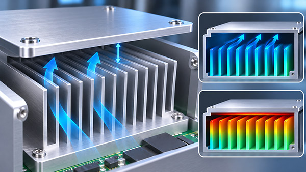
For OEM designers, fin-to-cover clearance should be considered part of the complete cooling system rather than a minor packaging dimension.
What Is Fin-to-Cover Clearance?
Fin-to-cover clearance is the distance between the outer envelope of the Heat Sink Fins and the nearest enclosure surface or protective component.
Depending on the cooling system, this gap may influence:
Air movement near the fin tips.
Mechanical interference during assembly.
Available space for manufacturing tolerances.
Possible vibration-related contact.
Serviceability and cleaning access.
The required clearance depends on the heat sink profile, airflow design, enclosure geometry, and operating conditions.
1. Mechanical Clearance Is Different from Airflow Clearance
A small gap may be mechanically sufficient to prevent direct contact under ideal conditions.
However, that does not mean the same gap provides adequate airflow.
If air must enter or leave through the space above the fins, a restrictive cover may limit circulation.
Conversely, in a carefully designed duct, a close-fitting cover may help guide airflow through the fin channels.
The thermal effect therefore depends on the intended airflow path.
2. How Does the Cover Affect Natural Convection?
Natural convection relies on the movement of warmer, less dense air away from heated surfaces.
When a cover restricts this movement, the warm air may remain near the heat sink instead of being replaced by cooler air.
This can reduce cooling performance, particularly when the surrounding enclosure has limited ventilation.
Designers should evaluate the orientation of the fins, the location of ventilation openings, and the available space for air circulation.
3. How Does the Cover Affect Forced-Air Cooling?
In a forced-air system, a fan or blower moves air through the cooling structure.
The cover may act as a duct boundary, changing airflow distribution across the fins.
If the cover is positioned incorrectly, it may create a restriction or allow unwanted airflow bypass.
The final result depends on fan pressure, fin geometry, duct seals, and enclosure resistance.
A small fin-to-cover gap should not be described as universally beneficial or harmful without testing the actual airflow arrangement.
4. Include Extrusion and Assembly Tolerances
The nominal fin height is only one dimension in the clearance calculation.
Other contributors may include:
Variation in extruded fin height.
Base thickness and machining variation.
Profile twist or bow.
Mounting-hole position.
Bracket and cover tolerances.
Assembly positioning variation.
Expected mechanical deflection.
The designer should assess the clearance under the applicable worst-case or statistical tolerance method selected for the project.
5. Account for Vibration and Thermal Movement
Industrial equipment may experience vibration from motors, transportation, or nearby machinery.
If the fin tips are too close to the enclosure, dynamic movement could cause contact or noise.
Thermal expansion can also change dimensions during operation.
The available clearance should be reviewed under the intended environmental and mechanical loads.
Fin Clearance Design Checklist
| Design Factor | Possible Problem | Recommended Review |
|---|---|---|
| Nominal gap | Insufficient clearance | Define minimum functional space |
| Profile tolerances | Fin envelope variation | Check maximum occupied dimensions |
| Natural convection | Restricted warm-air movement | Evaluate installed orientation |
| Forced airflow | Pressure loss or bypass | Review complete duct geometry |
| Vibration | Fin-to-cover contact | Assess relative mechanical movement |
| Maintenance | Limited cleaning access | Review service requirements |
How to Validate the Clearance
Thermal validation should use a representative enclosure with the intended cover, fan, heat sink, and mounting hardware installed.
Engineers can compare component temperatures and airflow conditions before and after relevant cover or duct changes.
Mechanical inspection should confirm that the heat sink remains within its permitted envelope under the specified assembly conditions.
Custom Extrusion Heat Sink Manufacturing
KINGKA supplies custom extrusion heat sink solutions for industrial electronics and OEM equipment.
Extruded profiles can be evaluated for different fin heights, overall dimensions, mounting features, and secondary machining requirements.
Customers should provide enclosure drawings, thermal loads, airflow conditions, and critical clearance requirements when discussing a custom profile.
Develop a Heat Sink for a Compact Enclosure
Share your equipment layout, maximum available height, mounting drawing, and cooling requirements with KINGKA to review the manufacturing feasibility of your extrusion heat sink.
Frequently Asked Questions
Should a heat sink cover be as close to the fins as possible?
Not necessarily. Close clearance may help certain ducted systems but can restrict other airflow arrangements.
Does fin height tolerance affect enclosure fit?
Yes. The maximum fin envelope and other dimensional variations should be included in clearance evaluation.
Can a protective grille reduce heat sink performance?
It can introduce airflow resistance, depending on its geometry and placement. The installed cooling system should be tested.
Can a standard extruded heat sink be modified to fit a cover?
Some dimensional changes may be possible through profile selection or machining, while others require a different extrusion cross-section.