

A single aluminum heatsink may be used to cool several electronic components mounted on the same circuit board or mechanical assembly. However, those components do not always have identical package heights or contact conditions.
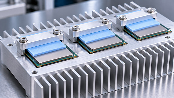
Thermally conductive pads can help bridge gaps between the components and the heat sink base, but the final compression of each pad must be considered carefully.
For OEM manufacturers, controlling thermal pad compression is an important part of achieving consistent contact across multiple heat-generating devices.
Why Do Multiple Components Create an Interface Challenge?
Electronic assemblies may contain processors, power transistors, memory devices, or voltage regulation components with different package dimensions.
When one extruded aluminum heatsink covers several components, the available gaps between the component surfaces and the cooling base may vary.
These variations are influenced by:
Component package height tolerances.
PCB thickness and flatness.
Component mounting and soldering conditions.
Heat sink base geometry.
Mounting hardware and assembly tolerances.
Thermal interface material thickness.
Without appropriate design, one pad may experience excessive compression while another may remain insufficiently compressed.
What Is Thermal Pad Compression?
A thermal pad is a compliant material placed between a heat-generating component and a cooling surface.
When the assembly is secured, the pad deforms to accommodate the available gap.
The compression behavior depends on the pad's material properties, thickness, contact area, and mechanical loading.
Manufacturers may specify acceptable compression ranges or pressure-deflection characteristics for particular products.
These requirements should be obtained from the selected material's technical documentation rather than applying one universal compression percentage.
1. Define the Available Gap
The first step is to determine the expected distance between each component and the corresponding heat sink contact surface.
This calculation should include dimensional tolerances across the assembly.
For example, the nominal gap may be affected by component height, the location of the heat sink mounting plane, and the geometry of any machined contact features.
The design should consider the smallest and largest expected gaps, not only the nominal condition.
2. Select the Pad Thickness
The thermal pad must be thick enough to establish contact under the largest expected gap.
At the same time, it should not experience unacceptable compression at the smallest gap.
Pad selection therefore requires a balance between gap coverage, contact pressure, and thermal resistance.
A thicker pad may accommodate larger variations but can introduce a longer heat conduction path.
3. Consider Pad Stiffness
Two thermal pads with the same nominal thickness may require different forces to achieve the same compressed thickness.
A relatively stiff pad can transfer greater mechanical loads into the electronic package and supporting circuit board.
A more compliant pad may reduce some mechanical loading, but its thermal and long-term performance must still be evaluated.
The complete pressure-deflection behavior should be considered when several pads share the same mounting structure.
4. Avoid Uneven Loading
When one pad is significantly thicker or stiffer than the others, it may influence the position of the heat sink during assembly.
In some designs, this can reduce contact pressure at another critical thermal interface.
The interaction between individual pads, mounting screws, and the stiffness of the cooling base should be reviewed together.
The solution may involve different pad specifications, controlled contact heights, or other mechanical design changes.
5. Evaluate Machined Contact Features
An extruded heat sink provides an integrated base and fin structure.
Secondary CNC machining can create selected contact steps, recesses, or mounting features where appropriate.
Such features may help adapt the base to components with different heights.
However, machining changes can affect base thickness, heat spreading, and manufacturing cost.
The final geometry should satisfy both thermal and mechanical requirements.
Thermal Pad Selection Checklist
| Parameter | Engineering Concern | Required Review |
|---|---|---|
| Nominal pad thickness | Gap coverage | Compare against assembly stack-up |
| Compression range | Contact pressure and deformation | Follow material supplier data |
| Pad stiffness | Mechanical load on components | Review pressure-deflection behavior |
| Thermal resistance | Component temperature rise | Evaluate at actual compressed condition |
| Component height | Different interface gaps | Include dimensional tolerances |
| Base geometry | Uneven contact and spreading | Check machined features and flatness |
| Mounting system | Load distribution | Review fastening and structural stiffness |
What Happens If the Pad Is Overcompressed?
Excessive compression may increase mechanical loading on the component or circuit board.
Depending on the material, it may also lead to deformation beyond the intended operating range.
Pad behavior should be evaluated using the manufacturer's specifications and representative assembly testing.
What Happens If Compression Is Too Low?
Insufficient compression may prevent consistent contact with the mating surfaces.
This can introduce additional thermal resistance and increase component temperature.
The actual effect depends on the pad material, surface condition, and operating environment.
How Should OEM Engineers Validate the Assembly?
Testing should use representative production components, thermal pads, mounting hardware, and heat sink geometry.
Engineers may evaluate the assembled dimensions, contact conditions, component temperatures, and mechanical loading.
For critical products, repeated assembly or thermal cycling may also be relevant.
Any chosen inspection method should be compatible with the component and thermal pad specifications.
Custom aluminum heatsinks for Multi-Component Cooling
KINGKA provides custom aluminum heatsinks with extrusion and CNC machining options for OEM electronics and industrial equipment.
Depending on the design, finished heat sinks can incorporate mounting holes, machined contact surfaces, and application-specific dimensions.
OEM customers should provide component drawings, thermal requirements, interface material information, and assembly constraints for manufacturing review.
Develop a Custom Multi-Device Heat Sink
Need a single extruded aluminum heatsink for several electronic devices? Share your component heights, contact areas, mechanical drawings, and thermal targets with KINGKA.
Frequently Asked Questions
Can different thermal pads be used under one heat sink?
Yes, when the complete assembly has been engineered to accommodate their thicknesses, stiffnesses, and thermal characteristics.
Is a thicker thermal pad always better for uneven component heights?
No. Greater thickness may improve gap coverage but can increase thermal resistance and change mechanical loading.
Can CNC machining improve multi-component contact?
It can provide application-specific contact features, subject to thermal, mechanical, and manufacturing requirements.
Should thermal pad compression be checked during prototype testing?
Yes. Representative assembly conditions help verify contact, mechanical loading, and thermal performance.