

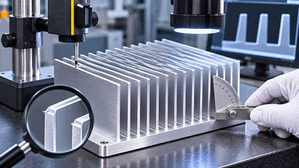
Precision aluminum Heat Sink Fins are important to the performance and manufacturing consistency of a Skived Fin Heat Sink. Since skiving forms thin fins directly from the base material, quality inspection must consider more than the overall dimensions of the finished block.
Fin height, pitch, thickness, tilt and edge condition can influence airflow clearances, mechanical handling and the fit of the cooling component inside electronic equipment.
For OEM buyers, defining the necessary inspection criteria early helps reduce ambiguity during prototype approval and repeated production.
How Are Skived Aluminum Heat Sink Fins Formed?
Skiving uses a controlled cutting and forming operation to raise thin layers of metal from a solid workpiece.
Unlike individually bonded fins, skived fins remain connected to the base through the original aluminum material.
The final geometry depends on the cutting conditions, material properties, tool configuration and forming process.
Because many fins are produced in sequence, consistency across the complete array is an important manufacturing consideration.
1. Fin Height Inspection
Fin height is commonly measured from a defined reference plane or base surface to the fin tip.
Variations in height can influence the overall occupied space and the position of the fin tips relative to nearby covers or ducts.
Height differences may also influence local surface area and airflow conditions.
The drawing should define the relevant datum and permissible height range.
For especially thin fins, the inspection process should avoid introducing measurement forces that bend the fin.
2. Fin Pitch Consistency
Fin pitch describes the distance between successive fins measured using a defined reference position.
Pitch variation may alter the clear gap between adjacent fins.
This matters when the cooling system uses a dense array with narrow airflow channels.
Engineers should distinguish between the nominal pitch, minimum open gap and total fin count.
These are related characteristics but not interchangeable specifications.
3. Fin Tilt and Orientation
Skived fins are raised during manufacturing and may have an intended angle relative to the base.
Variation in that angle can change channel geometry or the occupied envelope of the array.
Some tilt is part of the intended manufacturing geometry, so a fin should not automatically be considered defective simply because it is not perfectly vertical.
The acceptance requirement should describe the approved orientation and allowable variation.
4. Fin Thickness
Fin thickness influences metal conduction, stiffness and the available open gap.
Because thin fins can deform under contact pressure, the inspection method must be suitable for the part geometry.
Optical methods may be useful where contact gauges could disturb the fin shape.
The selected method should be appropriate for the required tolerance and access conditions.
5. Burrs and Edge Condition
Cutting and forming operations may create local edge irregularities or burrs.
Depending on their location, these features can affect handling, cleaning and assembly.
Large protrusions may also interfere with adjacent structures or change narrow channel clearances.
However, a requirement such as "no burrs" should be defined using an appropriate acceptance method.
The inspection plan should identify functionally important edges and the permitted condition.
6. Base and Mounting Features
Fin inspection alone does not confirm the suitability of the finished heat sink.
The base must also meet its required dimensions, flatness and mounting specifications.
CNC machining may be used to create holes or contact features after the fin-forming process, depending on the approved manufacturing sequence.
Final inspection should therefore cover both the cooling array and functional mounting surfaces.
Skived Fin Quality Inspection Checklist
| Feature | Purpose | Possible Inspection Method |
|---|---|---|
| Fin height | Check cooling envelope and dimensional consistency | Suitable optical or dimensional measurement |
| Fin thickness | Verify material geometry | Non-deforming dimensional inspection |
| Fin pitch | Check array spacing | Optical comparator or suitable measuring system |
| Fin tilt | Check orientation and minimum clearance | Profile measurement |
| Fin count | Verify drawing requirement | Visual or optical counting |
| Burrs | Identify unacceptable edge conditions | Visual or magnified inspection |
| Base flatness | Support thermal contact | Appropriate surface measurement |
| Mounting holes | Verify assembly compatibility | Dimensional inspection against datums |
Should Every Fin Be Measured?
The required inspection scope depends on the product specifications, process capability and customer acceptance plan.
Some features may be verified using representative sampling, while critical dimensions may require more extensive inspection.
For an initial prototype, the inspection plan may include a detailed dimensional review before a reduced routine plan is agreed for production.
Any sampling approach should be approved according to the project requirements.
Why Manufacturing Data Matters
For repeat production, the manufacturer should control the relevant skiving conditions and maintain suitable quality records where specified.
If the fin geometry changes unexpectedly, the supplier may need to investigate material variation, tool condition or process settings.
Corrective actions should address the cause of the variation rather than relying only on final sorting.
Precision skived fin heat sink Manufacturing
KINGKA provides aluminum skived fin heat sink manufacturing and customization for OEM electronics applications.
Engineering drawings can define fin geometry, base dimensions, mounting requirements and the inspection criteria relevant to the finished component.
Specify Custom Aluminum Heat Sink Fins
Need a skived heat sink with controlled fin thickness, pitch and height? Submit your drawings and production requirements to KINGKA.
Explore KINGKA Skived Fin ManufacturingFrequently Asked Questions
Which dimensions matter most for skived aluminum heat sink fins?
Fin height, pitch, thickness, orientation, fin count and the functional base geometry are common considerations.
Can fin tilt affect heat sink assembly?
Yes. Tilt changes the occupied envelope and may influence clearance between adjacent fins or nearby covers.
Are optical measurements useful for thin fins?
They can be useful where contact measurement could bend or disturb the fin geometry.
Should burr acceptance be specified in the drawing?
Yes, particularly where edge condition affects handling, installation or narrow airflow clearances.