

An aluminum cold plate with embedded tubing is commonly used to transfer heat from industrial power electronics into a circulating coolant. When specifying the metal tube, engineers often focus on outside diameter and routing layout. Tube wall thickness is equally important because it influences pressure integrity, forming behavior, coolant passage dimensions, and manufacturing consistency.
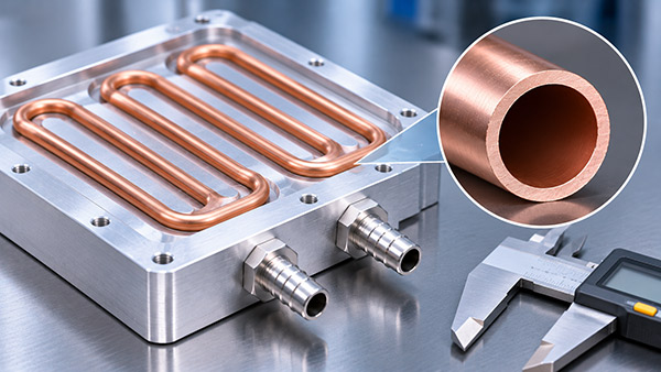
For OEM projects, the best tube wall thickness is not necessarily the thinnest or thickest available option. It must satisfy the thermal, hydraulic, mechanical, and manufacturing requirements of the complete cooling assembly.
What Does Tube Wall Thickness Mean?
Tube wall thickness is the distance between the outside and inside surfaces of the tubing.
For a nominally circular tube, the relationship between dimensions is:
Internal Diameter = Outside Diameter - 2 × Wall Thickness
For example, consider a hypothetical tube with an outside diameter of 8 mm and a nominal wall thickness of 1 mm.
Its nominal internal diameter would be:
8 - (2 × 1) = 6 mm
This simple geometric calculation assumes a uniform wall. Actual manufacturing tolerances and bending deformation must also be considered.
Why Wall Thickness Matters in Cold Plate Design
1. Internal Pressure Resistance
Coolant pressure creates mechanical stress within the tubing. A suitable wall thickness helps the tube withstand the specified operating pressure, pressure transients, and test conditions.
However, tube pressure capability cannot be established from wall thickness alone. Material properties, tube diameter, manufacturing method, bends, temperature, and applicable design rules must be reviewed together.
2. Coolant Flow Passage
When outside diameter remains constant, a thicker tube wall reduces the inside diameter.
This changes the flow passage area and can affect fluid velocity and pressure loss at a given flow rate.
For a circular passage, the internal cross-sectional area is:
A = π × Di² / 4
Because area depends on the square of internal diameter, relatively small dimensional changes can have a meaningful effect on the available flow area.
3. Tube Bending Behavior
Embedded tube cold plates often require multiple bends to route coolant around heat-generating components.
During bending, the outer wall experiences tensile deformation while the inner wall experiences compression.
Wall thickness, material temper, tooling, and bend radius influence the risk of excessive flattening, wrinkling, and wall thinning.
Wall selection should therefore be coordinated with the proposed tube routing before machining the cold plate grooves.
4. Heat Transfer Through the Tube Wall
Heat travels from the aluminum base, through the metal tube wall, and into the circulating coolant.
Thicker walls increase the conduction distance through the tube material, but the resulting thermal effect depends on tube material, contact quality, geometry, and coolant-side heat transfer.
A thinner wall is not automatically the better thermal choice if it creates pressure or manufacturing limitations.
Wall Thickness Design Trade-Offs
| Design Factor | Thinner Wall | Thicker Wall |
|---|---|---|
| Internal flow passage | Larger at the same outside diameter | Smaller at the same outside diameter |
| Material usage | Lower per unit length | Higher per unit length |
| Pressure design | Requires careful verification | May provide greater margin when other factors are equal |
| Bending | May require additional support against collapse | Can require greater forming force |
| Thermal conduction | Shorter wall conduction path | Longer wall conduction path |
| Manufacturing | Depends on available tube specifications | Depends on tooling and forming requirements |
How to Specify Tube Wall Thickness on an OEM Drawing
A complete drawing should specify the tubing material, nominal outside diameter, nominal wall thickness, relevant tolerances, and required bend geometry.
It should also identify the operating coolant, temperature range, maximum operating pressure, and applicable pressure-test requirements.
If the tube is supplied to a particular material or dimensional standard, that standard should be referenced accurately.
For critical applications, the manufacturer may need additional requirements for wall thinning after forming or inspection of representative bends.
Manufacturing Verification Checklist
Check incoming tube material and dimensions against the approved specification.
Confirm that the proposed bend radii are feasible.
Inspect representative bends for deformation and wall condition.
Verify that formed tubes fit the machined base grooves.
Perform agreed pressure and leak testing on the completed coolant path.
Validate thermal and hydraulic performance under relevant operating conditions.
Custom Aluminum Cold Plate Manufacturing with KINGKA
KINGKA offers custom aluminum cold plate manufacturing with embedded metal tubing for industrial electronics and OEM thermal management.
Customers can submit drawings, tube dimensions, coolant requirements, and operating conditions to discuss the manufacturing feasibility of a specified design.
Discuss Your Embedded Tube Cold Plate Design
Need a custom aluminum cold plate with specific tubing dimensions, bend geometry, and pressure requirements? Share your technical drawing and project specifications with KINGKA.
Explore Custom Tube Liquid Cold PlatesFrequently Asked Questions
Does a thicker tube wall always make a cold plate safer?
Not automatically. Pressure integrity depends on material properties, geometry, manufacturing quality, joints, and operating conditions, not wall thickness alone.
Does wall thickness affect coolant flow?
Yes. At a fixed outside diameter, wall thickness changes the internal diameter and flow area.
Can tube wall thickness change during bending?
Yes. The tube may experience local thinning and deformation. Inspection requirements should be based on the intended application.
Should tube wall thickness be included in the cold plate RFQ?
Yes. It helps the manufacturer evaluate tubing availability, forming feasibility, pressure requirements, and production cost.